LaGriT command file for these Examples.

QUADXYDefine an arbitrary, logical quad of points in 3D space with NDIM1 x NDIM2 number of nodes.
The four corners of the quad surface are defined in counter clockwise order ( the normal to the quad points is defined using the right hand rule and the order of the points).
The nodes can be connected using the createpts/brick/xyz command.
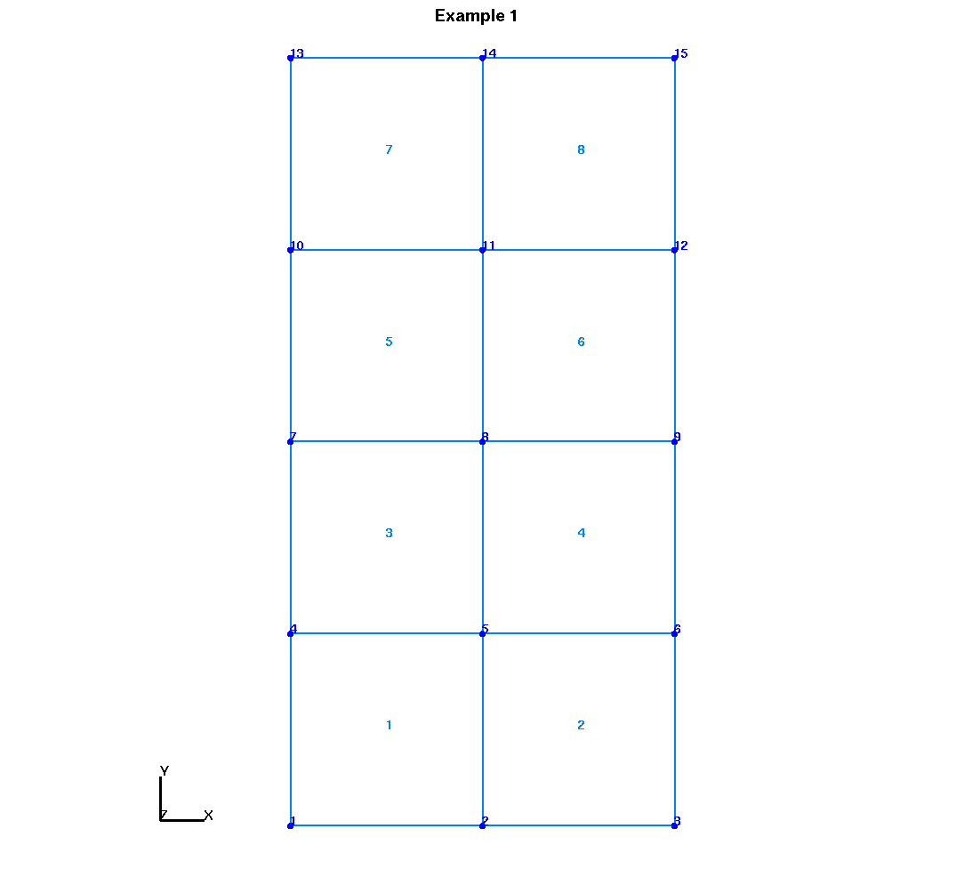
EXAMPLES: quadxy / 3 5 /0. 0. 0./10. 0. 0./10. 20. 0./0. 20. 0.
createpts/brick/xyz/ 3 5 1 /1,0,0/connect
Create a XY quad surface with 3 nodes in x direction and 5 nodes in y direction. See Example 1 image.
define X1 1.0
define Y1 2.0
define Z1 0.
define X2 15.0
define Y2 5.0
define Z2 0.
define X3 15.0
define Y3 5.
define Z3 25.
define X4 1.0
define Y4 2.
define Z4 25.
define / NX / 4
define / NY / 1
define / NZ / 10
quadxy / NX NZ/ X1 Y1 Z1 / X2 Y2 Z2 /X3 Y3 Z3 / X4 Y4 Z4
createpts/brick/xyz/ NX NY NZ /1,0,0/connect
Create a XZ quad surface with 4 nodes in x direction and 10 nodes in Z direction. See Example 2 image.
|
LaGriT command file for these Examples. |
||
|
quadxy_example1
|
quadxy_example2
|
quadxy_example3
|